Ayar Labs and GUC Complete Successful Thermal Co-Simulation Testing of Co-Packaged Optics

The CPO revolution is at our doorstep. But transforming data center interconnects requires overcoming new challenges in architecture, power delivery, mechanical design, and thermal management. Of these, thermal management has emerged as one of the most critical areas for successfully deploying co-packaged optics (CPO) in hyperscale AI environments.
Ayar Labs and Global Unichip Corp. (GUC) announced a strategic partnership to integrate CPO into GUC’s advanced ASIC design services. This collaboration paves the way for high-bandwidth, low-latency, power-efficient optical interconnects in next-generation AI, HPC, and networking applications where electrical signaling is reaching its limits.
One part of that talk that we’re particularly excited about is the thermal analysis of CPO in complex advanced multi-chip packaging design. Dr. Ian Cutress recently explored this on his TechTechPotato YouTube channel, and it was also a topic of discussion at Hot Chips.
Thermal instability has been a concern for CPO technology, so we were eager to collect this data. We jointly conducted thermal co-simulation of the advanced package design and determined the thermal floor map for the package and subsequent chiplets, including air- and liquid-cooled environments.
Since thermal stability has been raised as a concern for micro-ring-based CPO, we want to address it head-on. Our co-simulation data show that CPO can operate reliably within the thermal envelope of advanced multi-chip packages. We’re sharing these results to give hyperscalers the confidence to move forward with CPO deployments at scale.
Novel Design from Ayar Labs and GUC Enables over 100 Tbps Speeds
Let’s start with the new multi-chip package (MCP) design that integrates Ayar Labs’ TeraPHY™ optical engines into GUC’s advanced packaging and ASIC workflow. The new XPU MCP design replaces traditional electrical interconnects with Ayar Labs’ optical engines, which are attached directly to the MCP organic substrate. This architecture enables a full-duplex optical interface of more than 100 Tbps from the XPU package, an improvement of more than an order of magnitude over current XPUs.
UCIe-S provides bandwidth between the optical engines and the I/O chiplets over the MCP substrate. UCIe-A, on the other hand, is used for communication between the I/O chiplet and the main AI die over local silicon interconnect (LSI) bridges.
The scale of this design creates thermal challenges we must address. The complete package measures 105mm x 140mm, housing:
- 2 XPUs (25.69mm x 32.40mm each)
- 8 HBM4 memory modules
- 4 I/O chiplets
- 8 TeraPHY optical engines (12.5mm x 13.0mm each)
The +3 kW power envelope in a single package underscores the importance of thermal management and the need for optical engines to operate reliably alongside high-power AI processors. This complex multi-chip architecture requires sophisticated packaging. The design uses a 9-2-9 layer substrate structure to handle the complex routing requirements.
The design also addresses signal and power integrity challenges associated with the large-scale package. We perform thermal optimization at the XPU MCP level, while a stiffener design incorporates optical engines’ requirements and enables detachable fiber connections that meet mechanical stress and warpage requirements.
What is Thermal Co-Simulation and Why is it Important?
Thermal co-simulation is the combined simulation of electrical behavior and heat flow across a chip. It lets designers predict temperatures, hotspots, and reliability issues in integrated circuits (ICs) and packages under realistic operating conditions. The data ensures the entire system operates within required temperature specifications. This is critical for successful deployment.
In GUC’s thermal integrity design flow, we consider every chip’s power maps and perform thermal crosstalk and dynamic thermal co-simulation to ensure the MCP’s thermal integrity from early-stage through sign-off. This allows us to identify local thermal hotspots and the impact of thermal crosstalk on the optical engine.
Thermal co-simulation is crucial for GUC’s advanced ASIC workflows. In our joint analysis, the MCP includes multiple chiplets to analyze thermal crosstalk between adjacent chiplet dies. Any heat generated by the entire interposer complex may affect the optical engine’s performance.
Thermal modeling is needed to optimize optical engine performance. This joint technical exercise deliberately probes thermal hotspots and thermal crosstalk to evaluate overall CPO thermal stability in a realistic customer package form factor. Rather than avoiding the hard questions, we designed the simulation to stress the system and raise any potential concerns.
These findings are invaluable for assessing advanced packaging designs and collaborating with ecosystem partners to design optimal cooling solutions for AI server and switch applications at the most demanding Thermal Design Power levels. This testing allows us to do just that.
Ayar Labs and GUC’s Thermal Co‑Sim Testing
We performed three simulations: an analysis to determine thermal resistance targets for each chip component, plus testing of two different cooling solutions. One solution met spec, and one did not.
3D VC Heatsink test
We tested a standard air fin heatsink at airspeeds of 5 m/s and 6 m/s at 25ºC.
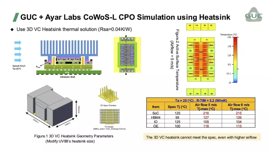
Figure 1. GUC + Ayar Labs CoWoS-L CPO Simulation using Heatsink
This did not meet spec, as the temperature significantly exceeded spec for all components except the I/O die.
Thermal Resistance Analysis
We analyzed the maximum junction temperature versus resistance curve to determine suitable resistance for the Chip-on-Wafer-on-Substrate with Local Silicon Interconnect (CoWoS-L) advanced packaging and optical engine to meet the temperature spec.
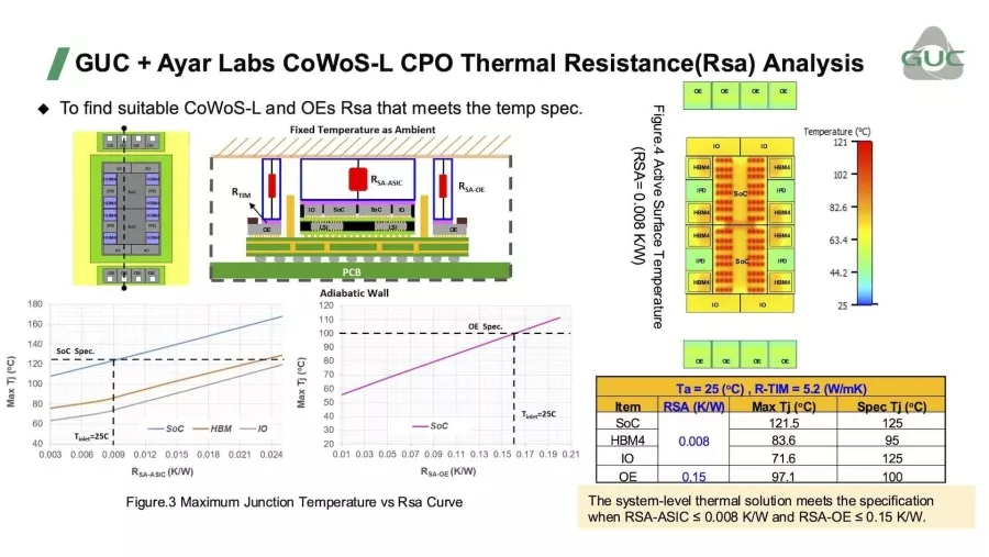
Figure 2. GUC + Ayar Labs CoWoS-L CPO Thermal Resistance(Rsa) Analysis
The system-level thermal solution successfully meets the specification when RSA-ASIC is ≤ 0.008 K/W and RSA-OE is ≤ 0.15 K/W. The cold plate design achieves these targets with pressure drops of 11.2 kPa for the ASIC cold plate and 18.8 kPa for the optical engine cold plate. This ensures efficient coolant flow while maintaining thermal performance.
Cold Plate Test
Finally, we tested an impingement-type cold plate thermal solution at 4.5 LPM.
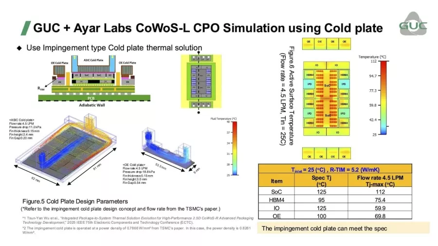
Figure 3. GUC + Ayar Labs CoWoS-L CPO Simulation using Cold Plate
This solution did meet spec. All components were below the temperature specifications.
Cold Plate Details
We selected the impingement-type cold plate for this application because it enables higher heat flux removal than conventional parallel-channel designs. The design uses optimized fin dimensions (thickness: 0.15mm, height: 2.4mm for the ASIC and 3.0mm for the optical engine) with thermal interface materials (K=5.2 W/mK) to achieve the required thermal performance.
This approach effectively dissipates the concentrated heat from multiple high-power chiplets while maintaining the optical engines within their operational temperature limits.
Key Results
- Determined the thermal resistance design targets for each chiplet for thermal sign-off constraints:
- HBM4 < 95ºC
- SoC < 125ºC
- Optical Engine < 100ºC
- Mapped the location of thermal hotspots.
- Showed that a traditional air heatsink does not work for this solution.
- Demonstrated that a real-world liquid cooling device meets the specifications needed.
These results point to a significant breakthrough in CPO deployment. Successfully maintaining optical engines under 100ºC while dissipating over 3kW TDP from a single package (with 1,500W coming from the AI processors alone) shows that CPO operates reliably with ample junction-temperature headroom, paving the way for the most demanding thermal environments.
Future Plans
Our next step will focus on dynamic workload simulation to further analyze thermal impact on CPO under real-world operating conditions. The tests we’ve shared here were based on static power assumptions, where each component’s power consumption remains constant. Systems ramp up from idle, spike during training or booting, and fluctuate based on user demand during normal operations.
Large numbers of users can cause heat spikes. A dynamic workload simulation will allow us to test our design under conditions more accurate to the real world. This will help us understand how the optics respond to sudden temperature changes and ensure the systems operate efficiently.
These thermal co-simulation test results demonstrate that CPO can operate reliably in high-power AI systems when paired with appropriate cooling solutions. As the industry continues to push the boundaries of compute performance and thermal design power, CPO will play a significant role in overcoming bandwidth and power limitations.
To learn more about implementing CPO in your next-generation AI infrastructure, contact our teams at ayarlabs.com/contact and guc-asic.com/en/contact.
Related Chiplet
- Optical Chiplet
- Reverse Gearbox Chiplet
- FlexGen Multi-Die Smart Network-on-Chip (NoC) IP
- Ncore Multi-Die Interconnect IP
- Integrated voltage regulator (IVR) chiplet
Related Blogs
- The Future of Chip Connectivity: UCIe and Optical I/O FAQs Explained
- The Future of Chip Connectivity: UCIe and Optical I/O FAQs Explained
- Breaking Through Bottlenecks: Executives from AMD, Ayar Labs, Cerebras, and Microsoft, Discuss the Future of AI Infrastructure with Optical I/O
- Co-Packaged Optics Step Into the Spotlight